 Portuguese
  English
  Spanish
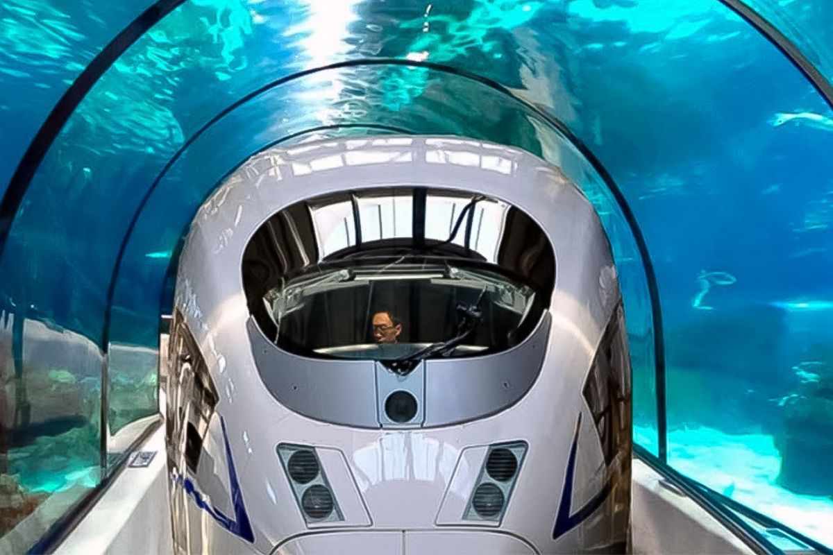


In The Depths Of The Channel Tunnel, The Invisible Enemy Of Compressed Air Is Controlled By Relief Ducts And The Service Tunnel To Ensure Safe Journeys.
When the Channel Tunnel was inaugurated in 1990, the world celebrated the feat of crossing the channel beneath the sea. But behind this historic work lies an invisible enemy that has challenged engineers since the first draft: the compressed air ahead of high-speed trains. Without control, this wall of air would create brutal resistance, making the journey uncomfortable, inefficient, and even dangerous.
To make the dream of connecting the United Kingdom and France by rail a reality, it required much more than digging tunnels at the bottom of the sea. It was necessary to learn to tame the air, transform the train into a calculated piston, and create systems capable of relieving pressure every meter traveled. This is where the decisive role of the 194 relief ducts, facing this invisible enemy every day, comes into play.
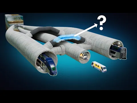
How The Train Becomes A Piston Inside The Channel Tunnel

To understand the invisible enemy of the Channel Tunnel, imagine a train entering a narrow tunnel at high speed.
-
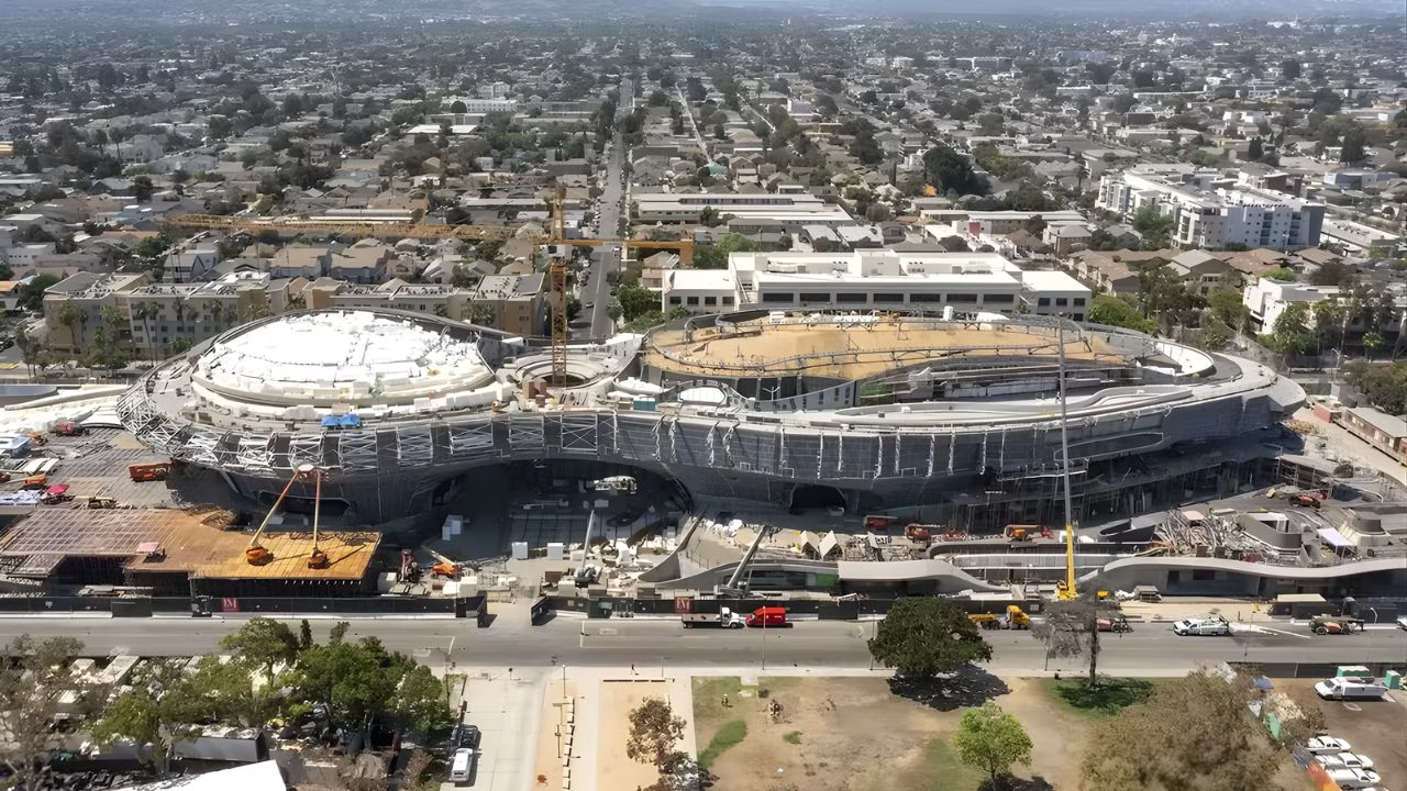
Created by George Lucas with over $1 billion, a futuristic museum in the shape of a spaceship with 1,500 curved panels is about to open in Los Angeles and will house one of the largest private collections of narrative art in the world.
-
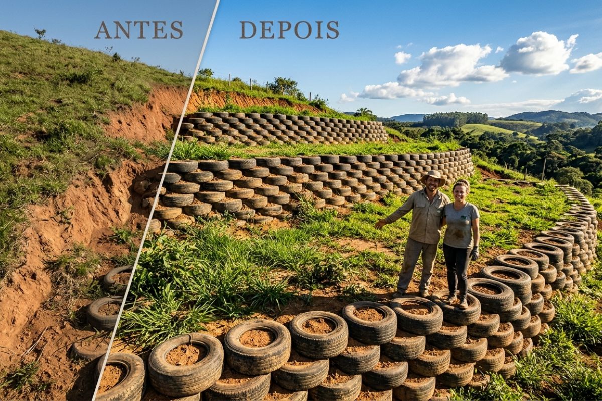
Couple shows how they built a retaining wall on their property using 400 old tires: sloped land turned into plateaus, tires are aligned, filled, and compacted with layers of soil, with grass helping in support and at almost zero cost.
-
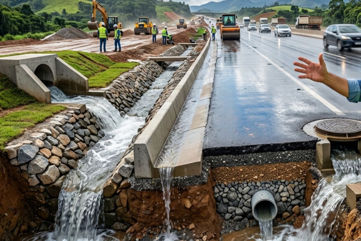
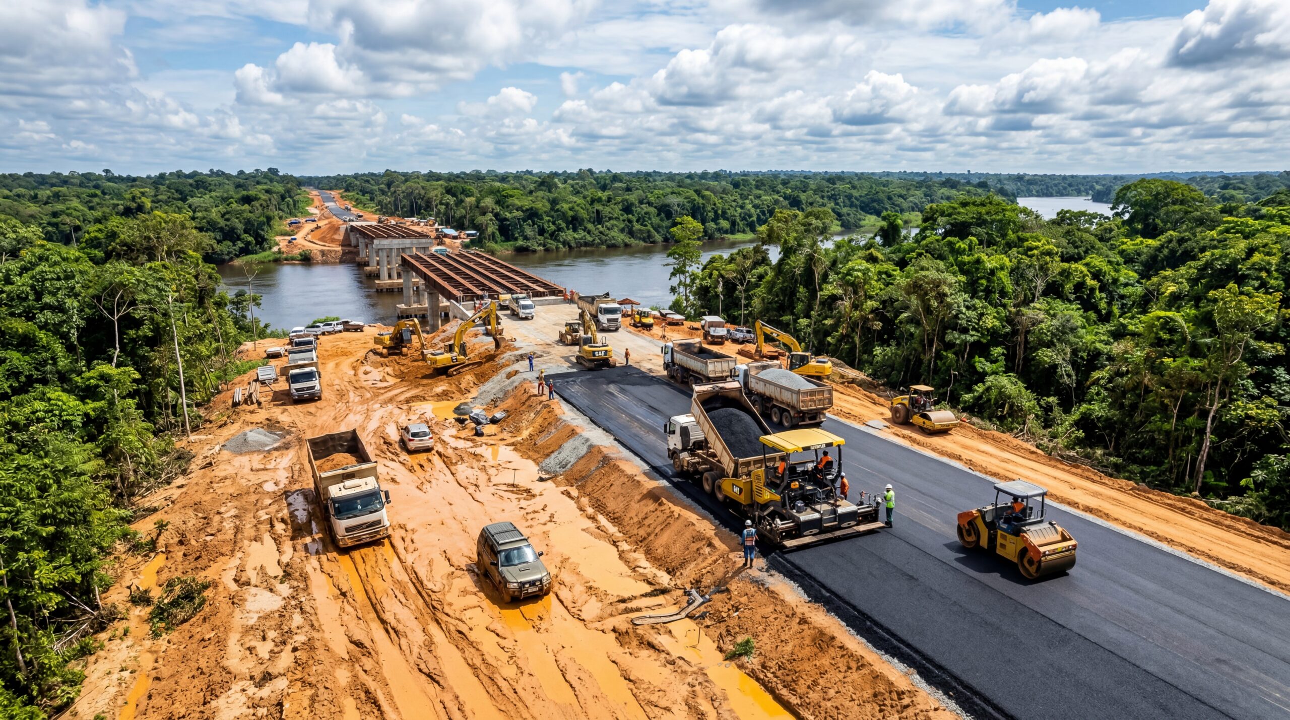
Engineer explains drainage during the rainy season: the difference between surface water and deep water, ditches, gutters, and water outlets on the road, as well as drains and drainage mattresses, to prevent erosion, aquaplaning, and flooding at the construction site today.
-
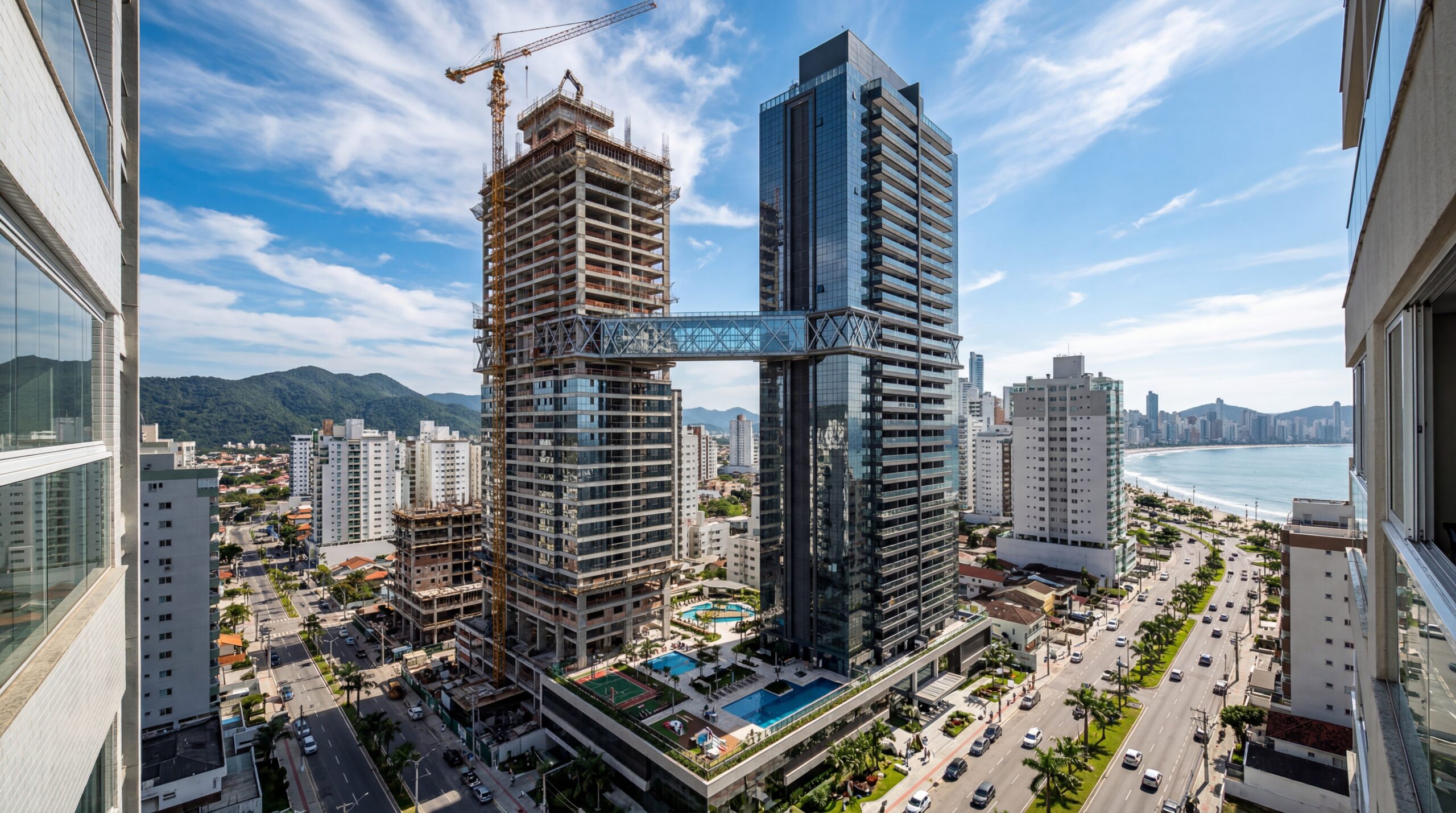
With 55 floors, 177 meters in height, a 15-meter walkway between the twin towers, ventilated facade, and 6,300 m² of leisure space, Ápice Towers already has one tower completed and another nearly at the top.
Ahead of it, the air has nowhere to escape and begins to be compressed, as if an invisible spring were being squeezed. The further the train advances, the greater the compression and the greater the resistance.
Without an intelligent solution, the train would be forced to “push” this compressed air all the time, losing efficiency, increasing energy consumption, and causing discomfort for passengers.
It is precisely this compressed air that becomes the invisible enemy of the system, creating an opposing barrier to the movement of the train.
The engineers’ response was to treat the tunnel as a large piston system with controlled relief. The 194 relief ducts were designed to allow some of this compressed air to drain between the tunnels, reducing the pressure in front of the train and balancing the flow.
Instead of an uncontrolled piston, the train operates in an environment where the air is managed, not just supported.
The Challenge Of Building A Tunnel Under The Seabed
Before facing the invisible enemy of compressed air, engineers had to overcome another obstacle: the very soil beneath the Channel.
The question was obvious and at the same time frightening: what if the tunnel collapsed under the immense pressure of the water? What if water found faults in the soil layers and invaded the tunnel?
The answer began with a thorough geological study. After decades of surveys and drilling, a layer of marine chalk with low permeability and good stability was identified, considered ideal for excavation.
Between the 1950s and 1980s, hundreds of wells were drilled in the seabed, combined with sophisticated geophysical surveys, until it was possible to draw a reliable map of the underground between England and France.
This geological base was essential to define the tunnel’s route, safe depth, and how to face not only water and external pressure but also the risks of fractures, collapses, and unpredictable failures.
From Napoleon’s Ideas To Giant Boring Machines

Long before the invisible enemy of compressed air became a real problem, the idea of a tunnel under the channel had already fascinated rulers.
In the early 1800s, at the height of the horse-drawn carriage era, Napoleon Bonaparte even analyzed a tunnel project linking France and England, lit by oil lamps. The war between the two countries buried the proposal, which would only be truly resumed in the 20th century.
When the modern Channel Tunnel project finally came to fruition, it was time for the machines to take center stage. Enter the TBMs, enormous tunnel boring machines that move like true mechanical caterpillars beneath the seabed.
These machines cut through rock, remove mud, and at the same time install concrete rings that line the tunnel, advancing step by step in a continuous operation.
Manufactured by companies such as The Robins Company and Kawasaki Heavy Industries, the TBMs were assembled in gigantic open caverns in Shakespeare Cliff, in the United Kingdom, and in Sangat, in France.
Each machine required weeks of assembly, testing, and adjustments before beginning its slow and precise journey under the sea.
Laser Guidance: When Two Tunnels Need To Meet In The Dark

Excavating under the sea meant not just advancing in the right direction. It was essential to ensure that the British and French excavation fronts met with millimeter precision, in the middle of the channel, at the exact depth of the chalk layer.
In an environment where GPS does not work, the solution was to combine classical topography, electromagnetic measurements, and laser technology.
Surveyors mapped a grid of coordinates uniting the two coasts, measuring angles between elevated points on the cliffs of Dover and the coast of Calais.
Using high-precision distance measurement instruments and, later, GPS support at the surface, engineers created a common reference system for both sides of the channel.
From this grid, coordinates were transferred from the surface to the seabed using the well plumb bob technique.
With the theoretical axis of the tunnel defined, the final step was to install a laser guidance system inside the tunnel itself. A laser theodolite positioned behind the TBM emitted beams to a light-sensitive target mounted on the machine.
Any deviation would cause the light point to move off the center of the target, and the computer would indicate corrections to the operator.
This way, even without seeing the other side, the TBMs were able to follow a curved and complex path, staying within the chalk layer and moving towards a historic meeting.
Safety, Cement Injection, And The First Handshake

Along the way, the invisible enemy was not only the compressed air but also the unpredictable behavior of the soil.
Cracks and fragile areas could cause collapses under high hydrostatic pressure, threatening lives and equipment.
To reduce this risk, engineers used a preventive strategy: the TBMs were equipped with special drillers to open exploratory holes ahead of the advance, at distances of up to 250 meters.
If the probing indicated bad conditions, grout was injected through these holes, consolidating the soil and strengthening the layer before the machine’s arrival.
With the service tunnel drilled first, this cement injection could also be done radially, preparing the ground for the main tunnels.
When the two fronts were about 100 meters apart, engineers opted for a “soft docking”: they first drilled a narrow hole connecting England and France, confirming the perfect alignment.
Then, a small pilot tunnel was excavated manually, allowing for the emblematic handshake between workers from both sides in December 1990. Only then did the French TBM break through the last barrier of soil, completing the service tunnel.
More Than A Tube: Cross Passages, Ventilation, And Evacuation
If you imagine the Channel Tunnel as a single straight tube connected end to end, the reality is much more complex.
The final design adopted two main tunnels and a central service tunnel, interconnected by cross passages every 375 meters.
Additionally, level crossings were created that divide the 50.5 km crossing into six operational sections.
This division allows trains to divert from one tunnel to the other in the event of maintenance or incidents, keeping part of the system operational even in emergencies.
The service tunnel, maintained at a higher air pressure than the main tunnels, serves as an access route for teams, an evacuation corridor, and the lung of the ventilation system.
Large axial fans send fresh air to the service tunnel, from where it is distributed to the traffic tunnels through vents and controlled doors.
In case of fire, the pressure difference helps prevent smoke and flames from invading the service tunnel, ensuring a safer escape and rescue route.
Heat, Compressed Air, And Temperature Control
In addition to the invisible enemy of air pressure ahead of the train, there is another challenge that cannot be seen but can be felt: heat.
When high-speed trains traverse the tunnel, friction with the air generates a significant amount of heat, which does not easily dissipate in the confined environment.
To prevent temperatures from rising to dangerous levels, a piping system carries chilled water through the tunnel, absorbing some of that heat and helping to maintain the temperature around 25 ºC.
Without this thermal control, operating conditions could affect both passenger comfort and equipment reliability.
It is the combination of ventilation, relief ducts, temperature control, and airflow engineering that keeps the invisible enemy under control, ensuring stable, quiet, and much smoother journeys than raw physics would allow.
A Journey Through The Channel Tunnel, Under The Gaze Of Engineering
On a real journey, the passenger boards in Coquelles, France, about 6 km from the coast, and heads towards the United Kingdom without noticing the complexity hidden in the walls around.
The route seems simple, almost straight, but in practice, the train follows a carefully planned path through the chalk layer, crossing level crossings, relief ducts, and invisible ventilation networks.
If any technical problem arises in a section, maintenance vehicles enter through the service tunnel, passing through robust doors and traversing the cross passages to reach the exact point of occurrence.
The operation is designed so that, whenever possible, part of the system remains active, even under unforeseen circumstances.
Under the sea, every meter of track is supported by engineering decisions that balance invisible forces, from the compressed air ahead of the train to the heat generated by the journey. This is how the Channel Tunnel transforms a hostile environment into a safe corridor between two countries.
And you, had you imagined that the greatest enemy of the Channel Tunnel is an invisible enemy made only of air, pressure, and heat?


Impressive engineering feat.