
 Portuguese
  Spanish
After the 2011 tsunami, the stayed bridge in Kesennuma Bay became the Kesennuma Bay Crossing Bridge, with floating cranes lifting steel modules at tide windows.
The stayed bridge of Kesennuma Bay became one of the most impressive projects of Japan’s coastal reconstruction: engineers erected a steel crossing in the middle of the sea, connecting large blocks with a margin of error measured in millimeters. What happened was the step-by-step assembly of the Kesennuma Bay Crossing Bridge, on the Sanriku coastal route, after the destruction caused by the Tohoku tsunami in 2011.
The challenge was almost cruel: the construction needed to advance in a site affected daily by tides, with offshore winds and the bay continuously used for aquaculture and local traffic. The solution was to “bring the bridge ready” to the sea, with prefabricated modules on land and super-heavy lifts organized in extremely short operation windows.
Why this stayed bridge needed to be born different

The Kesennuma Bay Crossing Bridge was not designed just as a shorter path over the bay. It was designed to maintain daily mobility and, at the same time, function as a relief and emergency link in critical situations, precisely because the old coastal route had been severely damaged in 2011.
-
Giant 3,600-ton Crane Breaks Two World Records by Installing World’s Largest Single-Piece Forged and Welded Hydrogenation Reactor, Weighing 3,037 Tons, in Chinese Petrochemical Plant in Just Six Days

-
$80 Million Bridge in Brazil Cuts Travel Time from 30 Minutes to 1 Minute, but Audit Reveals Major Flaws
-
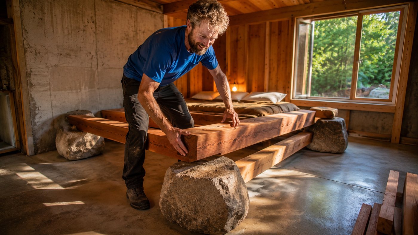
Man Builds Stone Bed with Granite Rocks and Hand-Sawn Cedar Beams, Home Extension Garners Over 437,000 Views on Bonus Bolts Channel

-
Brazilian Researcher Develops Color-Changing Roof Tile to Reduce Air Conditioning Use by Up to 15%


Furthermore, the bay is an important aquaculture area. This imposed limits on the type of intervention possible, reducing large fronts of “conventional” underwater construction and pushing the project towards a method that minimized working time over the water. That’s when the stayed bridge began to be built like a steel puzzle.
The invisible base: foundations, pillars, and the turn of the site
Before any module could rise, came the part that almost no one sees. The superstructure could only begin after the foundation system and the underwater concrete pillars were anchored to the geological base of the bay.
A critical phase was the removal of temporary structures and the cofferdam system with sheet piles, described as steel walls driven into the seabed to block water and create a dry working area. When this protective “shell” was removed, the foundations of the pillars appeared above the surface and the project entered the most decisive stage: raising the main tower of the stayed bridge.
Floating cranes and giant modules: the trick to save time

The main tower was not “manufactured at sea.” It was divided into large steel blocks, prefabricated on land, already with anchoring plates for the stays, connection details, and internal reinforcements. Then, these modules were transported by barge to the assembly point.
On site, heavy-lift floating cranes raised each segment, and the fitting occurred in a sequence from bottom to top. After each positioning, teams performed three-dimensional geometric alignment, fastening with high-strength bolts, and final welding at the site. A small deviation at the base could become a big mistake at the top, so alignment control was continuous throughout the process.
With this method of assembly in large blocks, offshore working time decreased without sacrificing the precision required for the next stage of the cable-stayed bridge: installing stays and advancing the deck.
The “real-time control” before the cables carry the structure

With the tower at the design height, the work entered the phase of installing the anchoring system and preparing the geometric axis that would guide the deck. As the anchoring points were already integrated into the steel modules, the teams began to verify position by 3D coordinates to ensure that the expected curve of the cable arrangement was respected.
A real-time monitoring of the tower’s geometry was also implemented, measuring tilt, horizontal displacement, and accumulated deformations due to its own weight, wind, and tide. In some cases, fine adjustments were made with corrections in the connections or temporary forces to bring the axis back to the design. The cable-stayed bridge only “becomes a bridge” in reality when the stays begin to carry load, and therefore this control was treated as a point of no return.
The advancement of the deck: overhanging over open water
Unlike viaducts with continuous supports, the cable-stayed bridge needed to span a large gap over open space. The solution was the cantilever method, a typical technique for long-span cable-stayed bridges: segments of the deck are installed gradually, advancing towards the center without support from below.
The deck segments were also manufactured on land and transported by barges. Floating cranes lifted each piece to the design position, temporarily connecting it to the already installed section, and then the first bundles of cables were placed and tensioned according to the design forces.
The sequence was symmetrical: for each segment on one side, a corresponding one on the opposite side. This helped maintain the balance of moments and reduce horizontal displacements of the tower under wind and tide. Each new segment changed the “balance” of the system, so the tensioning of the stays was adjusted step by step to control the overall geometry of the cable-stayed bridge.
The most critical moment: closing the span in the middle of the bay
When the two arms of the deck were close to the center, the most tense stage came: the closure of the main span. Before lifting the final piece, the engineers adjusted the tension of the stays to bring the ends closer within the exact predicted geometry, taking into account the temperature of the steel, offshore wind, and accumulated elastic displacements.
The closing segment was lifted by a floating crane and placed in the center with extremely high precision requirements. The text highlights that a mistake of just a few millimeters could generate residual stresses in the cable-stayed structural system. After the permanent connection, the tension of the cables was adjusted one last time to put the cable-stayed bridge in the designed working condition.
Tide windows and real life happening around

Another differentiator was the logistics. Since the area remained active for aquaculture and local traffic, the super-heavy lifts could not follow a continuous mechanical schedule. The operations had to be organized in short windows compatible with the real conditions of the bay.
This strategy of large prefabricated components reduced the time teams spent working directly over the water and decreased the area occupied by offshore activities. The cable-stayed bridge progressed without “stopping” the bay, a detail that is often overlooked but changes the entire level of complexity of the project.
What this cable-stayed bridge symbolizes in reconstruction
The Kesennuma Bay Crossing Bridge has been described as a vital link of the Sanriku Coastal Road, rebuilt after the 2011 tsunami to restore connectivity in northeastern Japan. By crossing the mouth of the bay, the new link shortened travel times and reduced dependence on coastal stretches vulnerable to large waves and earthquakes.
In the end, the cable-stayed bridge became more than just a crossing: a “steel cord” over the sea that represents engineering, precision, and recovery after the disaster.
If you saw such a structure in the middle of the sea, what would impress you the most: the lifting of the giant modules or the final fitting with a millimeter error?


I listened throughout the world in China agreatwall was constructed so many senturies past years ago after that no one thinks so to constructed a big thing like that but Japanese people are very special capable and fighting against natural disasters tausamni by building costle wall and this bridge remarkable achievements.
Kh